Demystifying 3D Graphics: Building a 3D Renderer from Scratch in a 2D Canvas
Written By  Idriss Douiri
12 min read
Building a 3D renderer from scratch is one of those projects where the payoff is unforgettable; staring at a 3D object rotating on screen, knowing exactly how every pixel got there.
That’s what we’re building today: a 3D renderer capable of displaying any complex shape, using nothing but a 2D canvas API.
<canvas></canvas>

<script>
  const canvas = document.querySelector("canvas")
  const ctx = canvas.getContext("2d")

  // Define a 1:1 area
  canvas.width = 400
  canvas.height = 400
</script>First, let’s define the coordinate system of our 3D world.
Unlike 2D coordinates, where (0, 0) is at the top-left and coordinates increase as you go right and down. In 3D, we use a world space where the origin (0, 0, 0) sits perfectly in the middle.
Normalized Device Coordinates (NDC)
NDC is a standard coordinate system in 3D graphics used to map those 3D coordinates to a 2D screen space. It is a mathematical cube where (0, 0, 0) is located exactly at its center, and all its axes range strictly from -1 to 1. Anything outside this range is clipped (ignored by the engine and not drawn).
We get our NDC values after mathematically projecting our 3D objects through our virtual camera.
Mapping this new NDC space to our final 2D screen space is straightforward. We simply multiply each point by half the canvas’s size and add that same amount again to shift the center. Don’t forget to reverse the y-axis to go from top to bottom!
Let’s test it:
- If x is exactly -1, then (x + 1) is 0 * w/2, which is 0 (the left edge).
- If x is 0, then (x + 1) is 1 * w/2, which is the middle of the canvas.
- If x is 1, then (x + 1) is 2 * w/2, which equals the full width of the canvas (the right edge).
Now that we understand our world coordinates, let’s define the points (vertices) that will form a 3D cube in world space, but instead of using a regular JavaScript object for each point, I want to encapsulate this logic into its own Vector3 class:
class Vector3 {
constructor(x, y, z) {
this.x = x
this.y = y
this.z = z
}
}
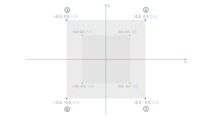
const cubeVertices = [
new Vector3(-0.5, -0.5, 0.5), // 0 bottom-left
new Vector3( 0.5, -0.5, 0.5), // 1 bottom-right
new Vector3( 0.5, 0.5, 0.5), // 2 top-right
new Vector3(-0.5, 0.5, 0.5), // 3 top-left
new Vector3(-0.5, -0.5, -0.5), // 4 bottom-left
new Vector3( 0.5, -0.5, -0.5), // 5 bottom-right
new Vector3( 0.5, 0.5, -0.5), // 6 top-right
new Vector3(-0.5, 0.5, -0.5), // 7 top-left
];You can visualize these 3D vertices as follows:
Orthographic Projection
Now we need a way to project our 3D points onto our flat 2D canvas.
For our very first projection, we will use a basic Orthographic Projection. In orthographic projection, objects do not shrink as they move further away. We simply flatten the 3D world by completely ignoring depth (the Z-axis).
Because we defined our cube’s 3D coordinates using values between -1 and 1, we can treat them exactly like NDC values! Let’s write a projection function that simply ignores z and maps our -1 to 1 x and y values directly to screen pixels using the formula we just learned:
function project(p) {
  const x = (p.x + 1) * canvas.width /2
  const y = (1 - p.y) * canvas.height /2
  return {x, y}
}
Then, inside a render function, let’s take each vertex, project it, and draw it as a point:
function render() {
 ctx.clearRect(0, 0, canvas.width, canvas.height)

 for (const vertex of cubeVertices) {
  const {x, y} = project(vertex)
  drawPoint(x, y)
 }

 requestAnimationFrame(render)
}

requestAnimationFrame(render)

function drawPoint(x, y) {
 ctx.beginPath()
 ctx.arc(x, y, 2, 0, Math.PI * 2)
 ctx.fill()
}
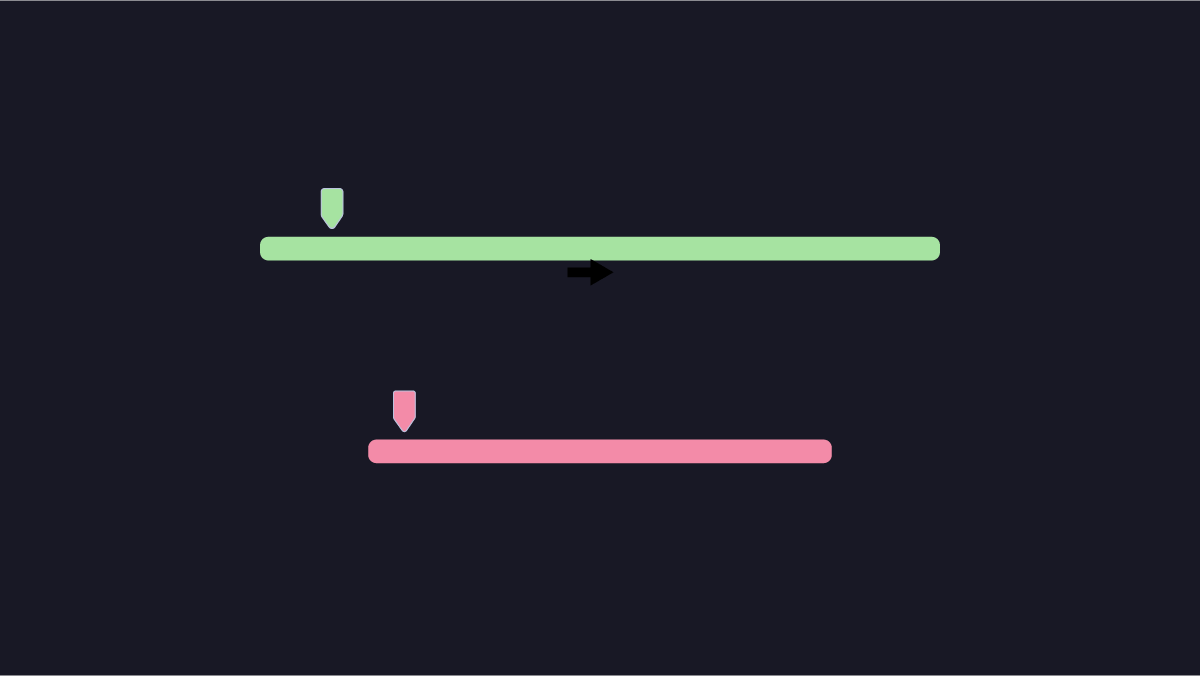
We can now see something, but we got just four points (a flat square). Because we completely ignored the Z-axis depth in our orthographic projection, the four points of the back face are drawn exactly behind the four points of the front face!
To make this look like a realistic 3D scene, we will eventually need to implement Perspective Projection. This is the math that makes farther points converge toward a vanishing point, causing distant objects to look smaller than closer ones.
But before we add that complexity, let’s prove our 3D cube is actually there. Let’s animate these points rotating in place to reveal that hidden back face and confirm our orthographic projection is working perfectly.
Rotation Matrix
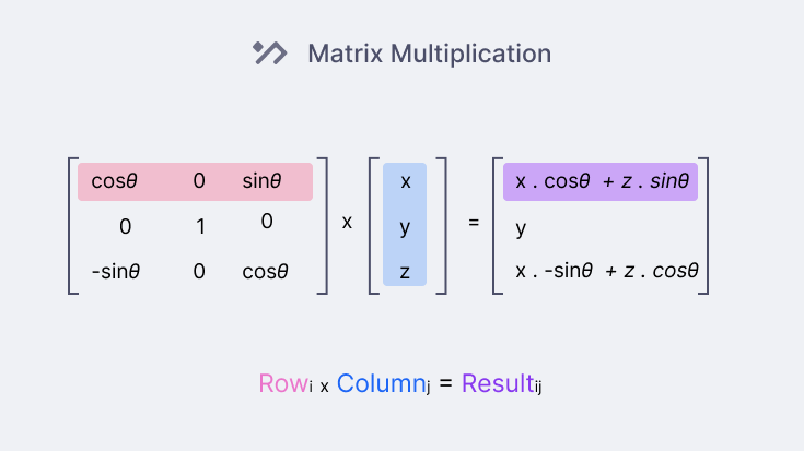
To rotate our 3D points, the standard mathematical approach is to multiply each point by a 3x3 Rotation Matrix. There is a specific matrix for each axis you want to rotate around (X, Y, or Z). The result of this multiplication gives us the point’s new, rotated 3D coordinate.
Here are all three rotation matrices:
Don’t worry about how these formulas are derived! You can simply plug them into your code, and they will work like magic.
To apply this rotation in code, we have to multiply our 3x3 matrix by each point. Since a point has three values (), we treat it as a 3x1 grid (called a column vector). Matrix multiplication simply involves multiplying the rows of the matrix by the column of our vector, as shown below:
Now, let’s add the rotation logic to our Vector class
class Vector {
 // ...
  rotateX(angle) {
  // cache expensive trigonometry calls
  const c = Math.cos(angle)
  const s = Math.sin(angle)

  return new Vector3(
    this.x,
    this.y * c - this.z * s,
    this.y * s + this.z * c,
  )
 }
 // We can do the same for rotateY and rotateZ as well
}
Now we can rotate every point before projecting it to the screen:
let angle = 0 // we can make an angle for each axis (e.g., cubeRotation = new Vector3(0, 0.2, 0.1)

function render() {
 //...
 angle += 0.1

 for (const vertex of cubeVertices) {
  const rotated = vertex.rotateX(angle).rotateY(angle).rotateZ(angle)
  const {x, y} = project(rotated)
  drawPoint(x, y)
 }
 //...
}
With this rotation in place, we can finally see the back face and visualize our 3D cube, even if it’s just 8 floating points right now.
As we mentioned, this is using orthographic projection, which lacks the illusion of depth, so let’s upgrade our engine to use perspective projection.
Perspective Projection
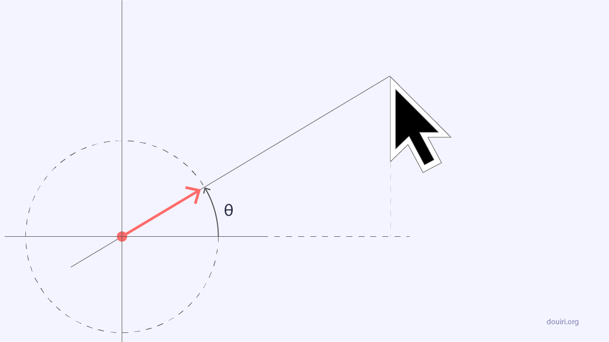
To understand the perspective projection, let’s visualize our 3D world. Imagine a camera (or an eye) that projects beams or lines through the screen (or window) and draws the intersection of the line with the screen; that intersection is our projected point.
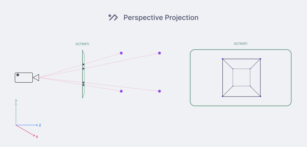
Now we need to figure out how to calculate this projection point.
Let’s zoom in and focus on one point and extract any useful information:
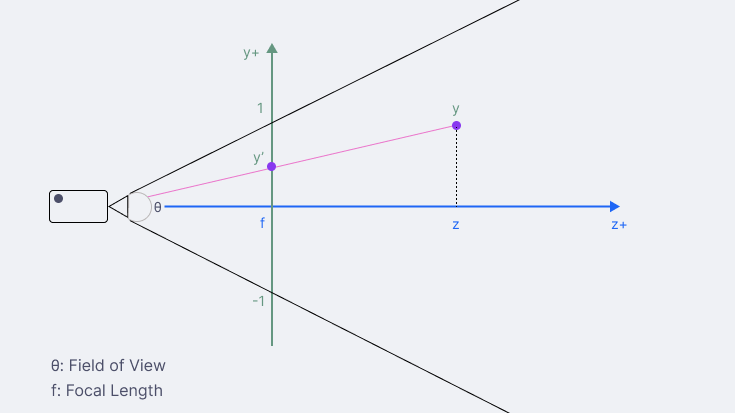
As we can see, by shooting our imaginary beam, we form a right-angle triangle that is perpendicular to the z-axis.
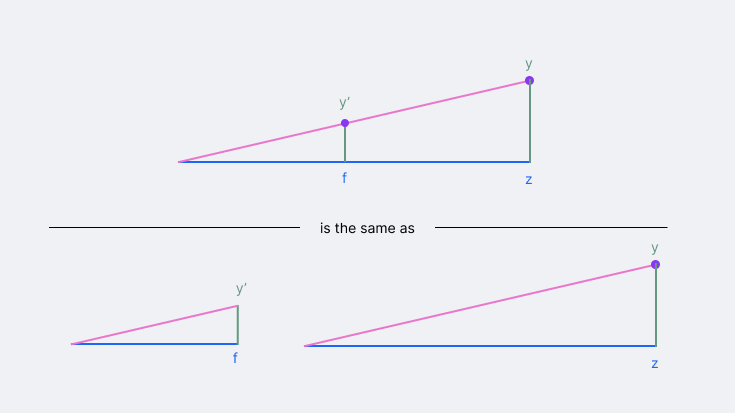
Actually, we get two right-angle triangles that share the same angle at the camera: one formed from the camera to the screen, and another from the camera to the 3D vertex. Because they share that angle, the rule of similar triangles tells us that the ratio of their sides must be equal:
Multiplying both sides by the focal length gives us our projection formula:
And applying the exact same logic to the horizontal axis:
But what is the value of f (the distance between the camera and the screen)?
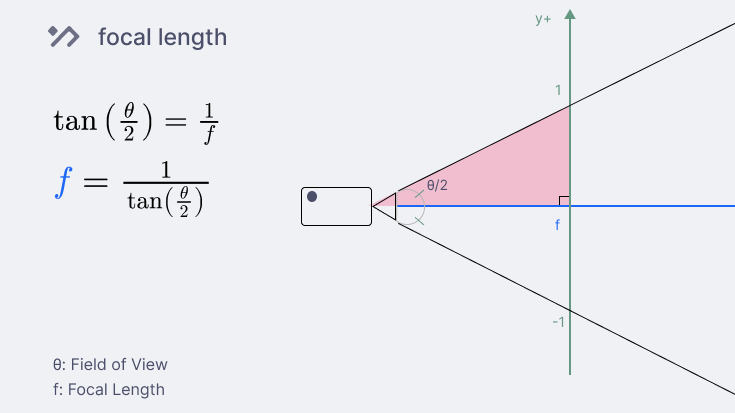
From the diagram, we notice that dividing the field of view by two gives us two connected right-angled triangles, so we can use trigonometry to figure out the camera distance:
We know that the tangent of an angle is its opposite divided by the adjacent: , which is in this case:
Finally, we move the focal variable to the left to get:
And that’s it, we now have all the values we need to update our projection function:
// narrow field of view means higher zoom

const fov = 90 * Math.PI / 180 // degrees to radians

const focal = 1 / Math.tan(fov / 2)

function project(p) {
  const xp = p.x * focal / p.z
  const yp = p.y * focal / p.z

  const x = (xp + 1) * canvas.width /2
  const y = (1 - yp) * canvas.height /2

  return {x, y}
}
With this updated projection logic, the vertices of the cube rotate around the camera, causing some points to fall outside the view. This is logical because (0, 0, 0) is both the center of the cube and the position of the camera.
To fix this, we can push the cube back in the z-axis after rotation so that we can see the full cube:
// inside render()
for (const vertex of cubeVertices) {
    const rotated = vertex.rotateX(angle).rotateY(angle).rotateZ(angle)
    rotated.z += 1 // push the cube in the z direction after rotating it around the center

    const {x, y} = project(rotated)
    drawPoint(x, y)
  }
At this point, we could connect each point with a line to get a wireframe version of our 3D cube, but let’s skip the boring lines and define the faces that will construct a mesh.
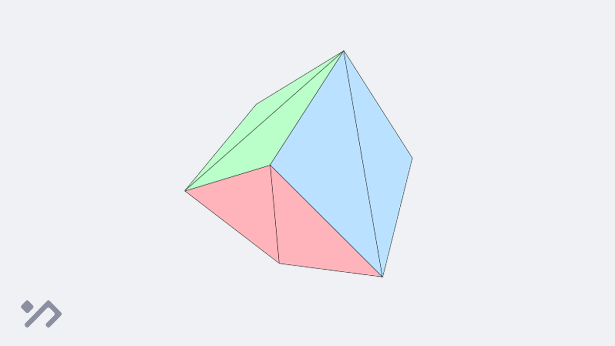
Triangular Meshes
A mesh is a collection of polygons, mostly triangles, that defines any 3D object.
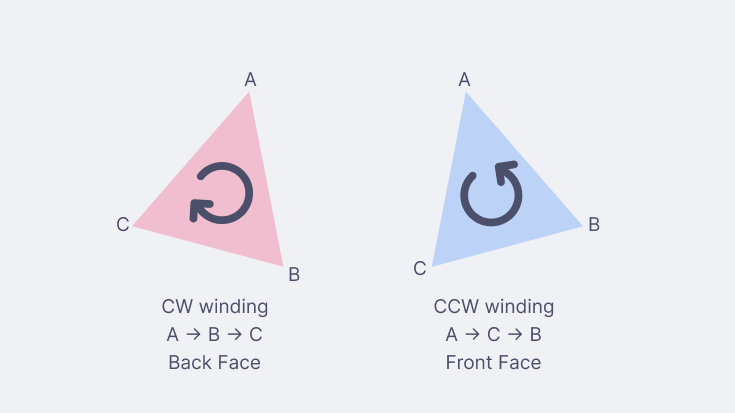
However, these triangles should be defined in a consistent sequence known as the winding order (either clockwise or counter-clockwise). This order defines the visible side of the triangle, as we only render triangles that are facing towards us. This process is called back-face culling and will be useful when coloring the triangles.
In other terms:
- winding order: which face is the front and which is the back
- back-face culling: don’t render back faces
In this case, I choose to work with counter-clockwise as the front face
To build our cube’s mesh, we need to define the triangles that make up its 6 faces (2 triangles per face). However, because these triangles share corners, we won’t hard-code the same coordinates over and over. Instead, we will create a list of indices and just reference the vertices by their index numbers to keep our code clean.
Drag to explore the cube’s vertices and their corresponding indices in the interactive visualization below:
const cubeMesh = [
    // FRONT
    0, 1, 2,
    0, 2, 3,
    // BACK
    5, 4, 7,
    5, 7, 6,
    // LEFT
    4, 0, 3,
    4, 3, 7,
    // RIGHT
    1, 5, 6,
    1, 6, 2,
    // TOP
    3, 2, 6,
    3, 6, 7,
    // BOTTOM
    4, 5, 1,
    4, 1, 0,
];Now we can update the render function to draw triangles instead of points:
class Vector3 {
  // ... previous code
  add(v) {
    return new Vector3(this.x + v.x, this.y + v.y, this.z + v.z)
  }
}

const cubePosition = new Vector3(0, 0, 1); // play around with the cube position

function render() {
  // ...

  for (const vertex of cubeVertices) {...}
  // doing the heavy math on each vertex ONLY ONCE
  const rotatedVertices = cubeVertices.map(vertex =>
      vertex.rotateX(angle).rotateZ(angle).rotateY(angle)
            .add(cubePosition) // push the cube back
  );

  // connecting the dots following our CCW winding order
  for (let i = 0; i < cubeMesh.length; i += 3) {
    const p1 = rotatedVertices[cubeMesh[i]];
    const p2 = rotatedVertices[cubeMesh[i + 1]];
    const p3 = rotatedVertices[cubeMesh[i + 2]];

    drawTriangle(
      project(p1),
      project(p2),
      project(p3)
    );
  }
  // ...
}

function drawTriangle(p1, p2, p3) {
  ctx.beginPath()
  ctx.moveTo(p1.x, p1.y)
  ctx.lineTo(p2.x, p2.y)
  ctx.lineTo(p3.x, p3.y)
  ctx.closePath()
  ctx.stroke();
}
We finally have a working 3D wireframe! The best part? This exact same code can render any 3D object as long as you provide its vertices and mesh. And stay away from complex objects, as CPUs are not designed for this.
However, we still haven’t used the back-face culling yet; that’s why if you try to fill each face with a color, you will see back faces get drawn over the front face.
The next article will cover solid coloring. Drop your email below so you don’t miss it!
Sign up to receive the latest tutorials and quizzes straight to your inbox.
Resizing the frame
Before I wrap up, let’s fix the stretching issue. At the start, we defined and worked with a 1:1 square canvas, but any other aspect ratio (e.g., 16:9) will stretch or shrink the objects.
Fortunately, there is a simple fix; Before we project the point, we will counter-scale one axis (x or y) by the canvas aspect ratio to cancel out the stretching:
const ar = canvas.width / canvas.height

function project(p) {
  const xp = p.x / ar * focal / p.z // divide x by ar
  const yp = p.y * focal / p.z

  const x = (xp + 1) * canvas.width / 2
  const y = (1 - yp) * canvas.height / 2

  return {x, y}
}
And that’s it! Now we have a responsive 3D wireframe renderer built with a 2D API, next we will cover coloring our objects.